
Understanding CNC Machining: A Practical Guide
Explore CNC machining processes, cutting tool selection, materials, cutting parameters, and practical ways to improve manufacturing efficiency.
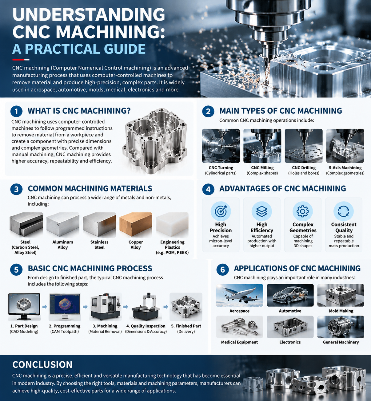
CNC machining is one of the most widely used manufacturing technologies in modern industry. From automotive components and aerospace parts to precision molds and medical equipment, CNC machining enables manufacturers to produce complex components with high accuracy, repeatability, and efficiency.
Whether you are new to CNC machining or looking to improve your production processes, this practical guide explains machining fundamentals, common operations, cutting tool selection, and best practices for reliable results.
What Is CNC Machining?
CNC stands for Computer Numerical Control. CNC machining is a manufacturing process in which computer-controlled machines follow programmed instructions to remove material from a workpiece and produce components with specified shapes and dimensions.
Unlike conventional manual machining, CNC machining automates machine movements, tool positioning, and cutting operations. This helps reduce human error and maintain consistent quality across production batches.
CNC Machine
Controls machine axes, spindle movement, and machining operations according to programmed commands.
CNC Program
Defines toolpaths, cutting movements, and machining parameters required to produce the component.
Cutting Tools
Remove material through turning, milling, drilling, threading, grooving, and other operations.
Workholding and Inspection
Secure the workpiece during machining and verify dimensional accuracy and finished-part quality.
The final result depends on the interaction between the machine, cutting tool, workpiece material, toolpath, workholding system, and cutting parameters.
Main Types of CNC Machining
Different machining operations are designed for different geometries and production requirements.
CNC Turning
Turning is primarily used to produce cylindrical components. The workpiece rotates while a cutting tool removes material from its surface.
Applications: Shafts, bushings, threaded components, and precision fittings.
Common tools: Turning inserts, external and internal turning tools, and threading tools.
CNC Milling
Milling uses a rotating cutting tool to remove material from a workpiece. It is suitable for flat surfaces, pockets, slots, contours, and complex shapes.
Applications: Housings, machine components, fixtures, and mold features.
Common tools: End mills, face mills, indexable milling cutters, and milling inserts.
CNC Drilling
Drilling creates holes in a workpiece. Boring and reaming may follow when tighter tolerances or improved surface finishes are required.
Common tools: Drill bits, indexable drills, boring tools, and reamers.
CNC Grooving and Parting
Grooving creates narrow recesses or channels. Parting separates a finished component from the remaining workpiece.
Common tools: Grooving inserts, parting inserts, and dedicated toolholders.
Five-Axis CNC Machining
Five-axis machining enables coordinated movement along five axes. It is particularly useful for complex geometries, angled surfaces, and components that would otherwise require multiple setups.
Typical applications include aerospace components, automotive parts, precision molds, and advanced engineering components.
Common Materials Used in CNC Machining
Workpiece material directly influences tool wear, cutting forces, heat generation, chip formation, and productivity.
Carbon and Alloy Steels
Widely used for shafts, mechanical components, industrial parts, and automotive applications. Tool grade and geometry should match the steel composition and hardness.
Stainless Steel
Offers corrosion resistance but may require careful control of cutting speed, heat, work hardening, and chip formation.
Aluminum Alloys
Generally offer good machinability and are commonly used for lightweight structural components, housings, and precision parts.
Cast Iron
Often suitable for turning and milling. Abrasive wear and dust management should be considered during machining.
Titanium Alloys
Used in demanding applications and often require careful thermal management, suitable cutting tools, and rigid machining setups.
Engineering Plastics
Materials such as POM and PEEK require appropriate tool geometry and careful control of heat, clamping pressure, and deformation.
The best cutting tool depends not only on the material name but also on its hardness, composition, condition, and the specific machining operation.
How to Choose the Right CNC Cutting Tool
Cutting tool selection is one of the most important factors in machining performance. The correct tool can improve dimensional accuracy, extend tool life, reduce downtime, and increase production efficiency.
01. Workpiece Material
Different materials require different tool substrates, geometries, and coatings. A tool designed for aluminum may not perform well when machining hardened steel.
02. Machining Operation
Turning, milling, drilling, threading, and grooving each have different cutting requirements. Select a tool suited to the operation and component geometry.
03. Insert Geometry
Insert shape, nose radius, rake angle, and chipbreaker design influence cutting forces, chip control, surface finish, and tool stability.
04. Carbide Grade and Coating
Cemented carbide grades and suitable coatings can improve wear resistance. The best choice depends on the workpiece, cutting conditions, and application.
05. Toolholder Rigidity
Stable toolholding helps minimize vibration and deflection. Excessive tool overhang can increase chatter and compromise surface quality.
06. Production Goals
Consider tool life, cycle time, surface finish, material removal rate, and total cost per component when evaluating tool performance.
Understanding CNC Cutting Parameters
Three fundamental cutting parameters strongly influence machining performance: cutting speed, feed rate, and depth of cut.
Cutting Speed (Vc)
The relative speed between the cutting edge and the workpiece surface, typically expressed in meters per minute (m/min).
Feed Rate (Vf)
The speed at which the cutting tool advances relative to the workpiece, commonly expressed in millimeters per minute (mm/min).
Depth of Cut (ap or ae)
The amount of material removed in a pass. Depending on the operation, this may refer to axial or radial depth of cut.
Feed Rate Formula for Milling
Vf = n × z × fz
Spindle Speed Formula for Turning
These formulas provide a starting point for calculating machining parameters. Actual settings should follow the cutting tool manufacturer's recommendations and account for machine rigidity, workpiece material, tool engagement, coolant conditions, and setup stability.
Avoid increasing cutting speed or feed rate without considering tool wear, cutting temperature, chip formation, and machine limitations.
Common CNC Machining Problems and Solutions
Understanding common machining problems helps operators identify their causes and make effective adjustments.
Excessive Tool Wear
Possible causes: Incorrect cutting parameters, unsuitable tool grade, abrasive materials, or excessive cutting temperature.
Solutions: Check recommended cutting conditions, evaluate the insert grade and coating, and inspect coolant delivery where applicable.
Poor Surface Finish
Possible causes: Tool wear, vibration, unsuitable feed rate, incorrect tool geometry, or machine instability.
Solutions: Inspect the cutting edge, verify toolholder rigidity, review the feed rate, and check the workholding setup.
Chatter and Vibration
Possible causes: Excessive tool overhang, weak clamping, insufficient machine rigidity, or unsuitable cutting conditions.
Solutions: Shorten tool overhang, improve clamping, and adjust cutting parameters systematically.
Poor Chip Control
Possible causes: Inappropriate chipbreaker geometry, incorrect feed, unsuitable cutting speed, or insufficient chip evacuation.
Solutions: Select an appropriate chipbreaker, optimize feed and cutting speed, and ensure safe chip removal.
Dimensional Inaccuracy
Possible causes: Tool deflection, thermal expansion, machine positioning errors, workpiece movement, or excessive tool wear.
Solutions: Verify tool offsets, inspect workholding, monitor tool wear, and check machine and workpiece temperatures where necessary.
Practical Tips for Improving CNC Machining Efficiency
Improving machining efficiency involves more than increasing cutting speed. A balanced approach helps improve productivity while maintaining quality and controlling costs.
- Choose application-specific tools. Match tool geometry and grade to the material and operation.
- Optimize cutting parameters. Change one variable at a time and record the results.
- Maintain stable setups. Use suitable workholding and minimize tool overhang.
- Monitor tool wear. Replace or index inserts before excessive wear affects quality.
- Improve chip evacuation. Use suitable chipbreakers and effective chip-removal systems.
- Reduce unnecessary tool changes. Review toolpaths and machining sequences to reduce idle time.
- Measure production results. Track tool life, cycle time, scrap rate, and surface quality.
- Review results regularly. Use production data to identify opportunities for improvement.
Small, controlled improvements can deliver meaningful gains over repeated production cycles.
Applications of CNC Machining
CNC machining supports a wide range of manufacturing industries, each with its own requirements for material selection, dimensional tolerances, and surface finish.
Aerospace
Structural components, lightweight parts, and complex precision components.
Automotive
Engine components, transmission parts, shafts, and precision housings.
Mold and Die Manufacturing
Mold cavities, cores, inserts, and precision tooling.
Medical Equipment
Precision instruments, equipment components, and selected implant-related parts.
Electronics
Enclosures, heat sinks, connectors, and precision mechanical components.
General Engineering
Industrial machinery parts, fixtures, hydraulic components, and custom components.
How to Build a Reliable CNC Machining Process
A reliable process combines suitable equipment, accurate programming, correct cutting tools, stable workholding, and consistent quality inspection.
01. Part Design
Define component geometry, dimensions, tolerances, and material requirements.
02. CAM Programming
Generate and verify toolpaths based on the selected machine and tooling.
03. Tool Selection
Choose suitable cutting tools, inserts, grades, and toolholders.
04. Setup and Machining
Secure the workpiece, set tool offsets, and run the machining program.
05. First-Piece Inspection
Confirm critical dimensions, surface finish, and process stability.
06. Production Monitoring
Track tool wear, cycle time, dimensional consistency, and opportunities for improvement.
Following a structured workflow helps reduce avoidable errors and supports repeatable production quality.
Conclusion
CNC machining is a powerful manufacturing technology that combines precision equipment, computer-controlled programming, and application-specific cutting tools. Understanding machining operations, material properties, tool selection, and cutting parameters helps manufacturers achieve better consistency and more efficient production.
The key is to treat machining as a complete system rather than focusing on a single variable. The right combination of machine capability, cutting tool, workholding, and process control can improve tool life, surface quality, and overall manufacturing performance.